Servicing an Child’s Electric Piano

Recently we were given a small toy piano. Grandmother has bought it from the flea market. It is a very common cheap toy. Somewhere during the road it has had some bumps because half of the keys did not produce any sound at all.

Open it I did.. And it revealed it’s secrets to me. A piece of circuit board was missing, actually the whole board was cut in half. Luckily I managed to find that missing piece.

20150722_001

20150722_003-pala

After some thoughts it was clear what to next. I inserted some cyanoacrylate and then I could go repairing those broken lines. I had to remove some coating that solder could stay in place.

20150723_001.jpg

Then some soldering and it looked like this:

20150723_011.jpg

When reassembly was done I recognised that it works!

20160317_232851.jpg

Honda Quad Starter Motor Repair

20160314_190640-quad

A friend of mine has a Honda quad. He told me that it’s starter motor has gave up a ghost. Naturally I had to crack it open. During dissassembly process turned out that my buddy had rolled the quad upside down a couple of times which explains the motor oil inside of starter motor. After some cleaning it was okay, except brushes which were totaled.

20160302_012-worn-brushes

Especially the another one. It looks like there has been some sparkling if I interpreter those craters right. 20160302_005-craters

My friend ordered the spare parts and a couple of days later them arrived.

20160314_175514-old-vs-new

During the assembly process we cleaned the anchor’s contact pads with sandpaper and a cordless drill. Not worthwhile compare to the lathe, but with limited resourses one must do what is doable..

20160314_180230-cleaned

Of course test drive went south. At first it started and ran fine, but during the second flight it stopped and did not started at all. No power, no nothing.  A closer inspection told me that somebody forgot to connect the ground wire to the motor. After reconnecting the quad ran fine and we back in business. Hooray!

Golf IV Brake Pedal Switch

I have a -06 Golf IV Variant and in one day it lit some warning lights to my instrument cluster.

001-Lights

EPC and Engine warning light lit and cruise control not working. Naturally I fired Google up and found that broken brake pedal switch can cause all of those problems. Running Ross Tech’s VCDS’s Measuring Values for cruise control confirmed the case. As one may know, cruise control needs to know when brake pedal is pressed that you don’t fight the engine. In the link provided is info how to check (with appropriate cable and downloaded VCDS-software) if the brake pedal switch is faulty or not. When I checked mine, it turned out that one of the two switches inside that brake pedal switch did not work. So I went to a local dealer and bought a new one for 20€. After fitting that in place I cleared all the DTC’s with VCDS and measured values again. All passed!

Some pictures of the process.

Here is the old one in position.

002-Faulty-One-In-Position

To remove it, it has to be twisted counter clockwise a bit.

003-Faulty-One-Twisted

Then it can be removed.

004-Faulty-One-Removed

Empty space.

005-Faulty-One-Removed#2

In hands.

006-In-Hands01

007-In-Hands02

008-Codes

009-Connections

A new one.

013New-One

Comparison.

014-Differences

VCDS: No braking.

015-VCDS-No-Braking

Braking. When braking, last two digits in Bin Bits-section must be 1, as they are now.

016-VCDS-Braking

Happy driving!

Cutters

I made a little cutters for cutting in half all kind of tablets. These are made of 3mm stainless steel sheet. Design is quite rough but I like them that way. They are meant to be in everyday use, so scratches are inevitable.

This is where I started, a sheet of metal and a freehand drawing.

001start

I welded two plates together with mig.

002halves_together

The drilling has started. I was going to make this with freehand.

004more_drilling

After some cutting.

007shaping#3

Separation.

008halves_separated

Things are getting in shape.

009rough_fitting#1

After that I milled slots to avoid misalignment. I milled only 1mm deep and bent the rest of halves. Since fitting halves to the milling machine was a bit difficult, I had to use a file also.

011milled_and_filed_washer

Here we are getting some rough shape.

012forming

I cut the blades to correct length and sharpened the other blade. From a drawing you can tell that I forgot to make that little curve that keep spring in position. But no worries, I got it in the other route.

016drawing_and_a_product

Since then I changed to a softer spring, made some guardian rails for it and put a new bolt for keeping halves together.

And polished them too.

018quite_ready

019quite_ready_other_side

And that’s it!


A New Toy

I have got my hands on a new toy. A dividing head.

dividing_head#01

But it lacks a tool for tightening objects in to the chuck. So we need to make one.

I took a 22mm diameter shaft and measured that square hole has a 10mm side. So I need to take 6mm off from each four side of  the shaft. Chuck has a wheel of 36 teeth and one can lock those teeth in position, one at the time. A quick calculation gives that when the first side is milled down 6mm, 18th teeth must be locked in and then milling can continue. After that 9th teeth locked and milled. And the last 18th teeth and milled. (Of course this can be done by 9 teeth at a time.)

Her we are in the middle of the process.

dividing_head#02

When all sides was milled, I bored a 13mm hole to the shaft. At first I used a center drill bit and a lubricant and then I gradually moved from 6mm to the big one.

hole_square_ready

All I have to do is to cut those 22mm and 13mm shafts in convenient length and make some adjustments that 13mm shaft don’t slide through the hole in 22mm shaft. And of course to do some grinding. Shafts are just some ordinary steel (st52 or something like that) so I am not expecting them to last too long, but time will tell that. On the other hand, I don’t believe that this dividing head (and its new tool) is going to get too much attention in its current location. Conveniently other chucks around the shop uses a different size of a square tool.

to_be_continued

Here is the Machine behind all of this..

setup

And no, I don’t own it, I just can borrow it and facilities around it.

Remember to use at least safety goggles (and Colin’s safety tie 😉 ) when using metal working machines!


Arduino, LCD and DS1820

As I mentioned in previous post, I might use those DS1820-sensors. And I did. Platform is the same, but enhanced by one little but mighty sensor. (Actually that sensor can be seen in previous post also.) Those little things are packed full of technology. They look like an ordinary transistor but that fools you a lot. They measure temperature quite a wide range (–55°C to +125°C) and convert analog readings to digital in no time. Multiple sensor can work in the same line because every one of them have it’s own unique serial number. They have also some other tricks in their sleeve, your favorite search engine will tell to you a lot about them.

When measured temperature is already converted to digital values, it is easy to get those values to Arduino, for example. Code is in Git. Code is released under gnu gpl 3 and is patched together from others contribution with a little bit of my own code.

This apparatus measure temperature values and shows them in Celsius degrees in LCD. Video below.


Arduino, LCD, Rotary Encoder and Ikea USB-LED

Update 21.5.2014: Here is the source code: https://github.com/renerento

Yes, Arduino, a piece of electronics that divides people. Some of us like it and some of us hate it. I like it.
Some time ago I bought 2 Arduinos at once and started to play with them. At first my goal was connect an Arduino to LCD and display some data on it. Then I realized that I have a rotary encoder and it would be fun to use that component as well. I digged code snippets from internet and found many ways to connect a rotary encoder to Arduino. Some of them used external capasitors for debouncing and I did not like that. Then I found Ben Buxton’s home page and used part of his code to make things click.

I also had some DS1820 temperature probes lying around and I decided to connect also them to Arduino. Maybe later more about that topic.

I found a simple aluminum enclosure. I modified it a bit for my components to fit in and started coding. As I am not a real coder, I simply searched code from the internet and modified it to suit for my applications.

This code does following:

When powered on string on LCD is displayed “LED dimming test”. After that display goes blank. When one rotates encoder LCD shows either string “Minimum value reached!” or up going numbers. Simultaneously with up going numbers the USB LED from Ikea starts to shine. The more the numbers grow the more LED shine, until it reaches the max value. When that happens LCD says “Maximum value reached!” User can decrease or increase the level of the numbers and brightness simple rotating encoder. Numbers change 5 unit per one encoder click, min is of course 0, max is 255.


Here are some pics and video.

LED_Dimming_Arduino_And_LCD_01

LED_Dimming_Arduino_And_LCD_02

LED_Dimming_Arduino_And_LCD_03


Changing Head Gasket for 2001 Clio

After I changed the cabin heater radiator to my ’01 Clio it was obvious that it was not enough. Overpressure in the cooling system was still a problem.  After driving, even if the car was not started in 12 hours, there was still so much pressure in the coolant system that if one opened it, a loud psssshhhh was heard. Next thing to do was to change a head gasket. Here are some pics of the process.

This was the starting point.
000-start-20120101_001

And some progress.

001-progress01-20120101_006

Cleaning cylinder head with sandpaper.

003-cylinder-head-cleaning02-20120101_024

Engine bay, top of the cylinders cleaned.

004-engine-bay02-20120101_027

Old gasket was a bit worn..

005-head-gasket01-20120101_009

Closer look.

006-head-gasket03-20120101_023

Comparison.

007-old-and-new-head-gasket-20120101_013

Fitting a new one..

008-new-head-gasket-fitting01-20120101_030

Tightening order.

009-head-gasket-tightening-order-20120101_032

After this point I kind of forgot to take pics.  But repairing succeeded and there was no more overpressure problems.

Sail on!

Toy Repair

I received a caterpillar toy for a repairing.

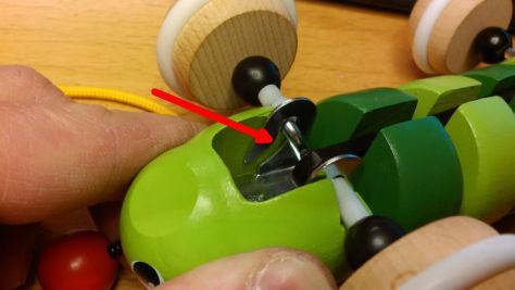
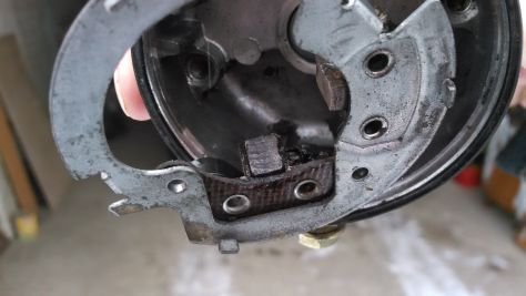
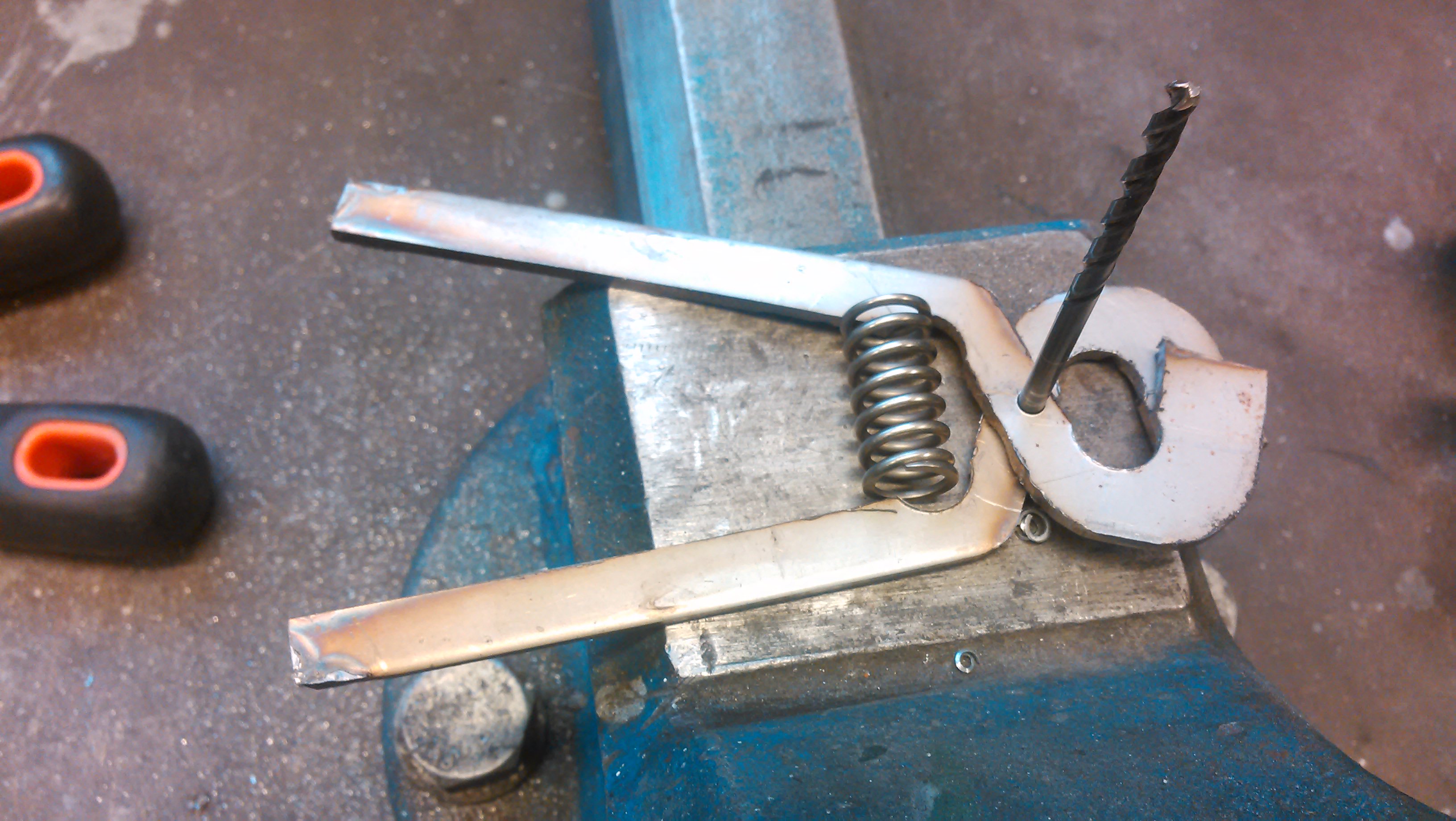
The metal slots holding up the front shaft keep getting stuck with the shaft’s cranking mechanism, and obviously stopped rotation. The other slot is clearly visible in this picture(red arrow), and also is the way I finally got it right. (Those short white plastic tubes.) At first I tried to make a sheet metal support inside of the metal support frame, but there was no room for that, shaft’s corners came in the way.

Caterpillar-II-20140228_003

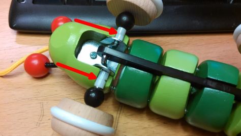
Here are the tubes, marked with red arrows. Plastic tubes don’t let the shaft move too much sideways and that way cranking mechanism can’t get in touch with the slots. It is not perfect, it still get stuck sometimes, but it is a way much better than before. I saw the owner’s test-drive and it went okay.

Caterpillar-I-20140228_002

Wooden wheels came off by just pulling hard enough and that way I could just slide in the tubes.

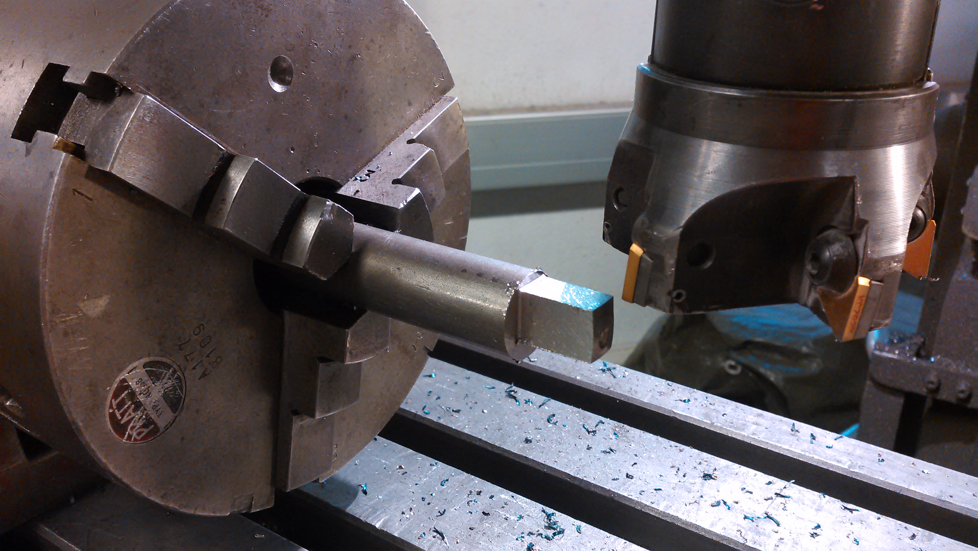
I found those plastic tubes from my part collection of a torn apart devices. Oh, and I had to use a file on the corners of the shaft to make things smoother.

Black bar’s other end is connected to caterpillar’s rear end.  The cranking mechanism makes the toy move like a real caterpillar. It is a quite clever invention, but execution is poor, tolerances are too big.

Toy was made by a good quality company, which make me kinda sad, they used to make good toys in the old days.. But on the other hand, one have to remember, this is the only one example of company’s many many products and maybe this was made on Monday.. 😉

Sail on!

2009 Mini Fuel Leakage

A friend of mine was on a holiday trip with his friends. They were going through the city I live at the moment. Their -09 Mini decided to burst some fuel on to the road only a couple of kilometers away from the place where I stay. 

First inspection showed nothing. But when we started the engine, the problem was clear: Pressurised rubber fuel hose had worn itself out towards the other hose and fuel was literally bursting out. It was Sunday and there was no place to go to get a spare part. And if shops were open, of course they had to order the spare part, I guess. We got an idea: What if we put some copper tubing into the broken area and secure joints with hose clamp? A quick Google search revealed that Mini’s fuel pressure is 4-6 bar. A reference call to a friend of mine confirmed that our idea was worth trying: The same trick has worked with a Mercedes, which has fuel pressure of 9 bar. My friend suggested that we should put two clamps per joint, total of four clamps. By doing that there should not be any problems. We managed to find some copper tube and hose clamps, and voila!

fixing-parts

Fixing parts, or what is left after the repair.

hose-fixed

Fixed! A friend of mine showing the results of our work.

The replacement part could be quite expensive, those proprietary connectors smells like a good amount of money..

difficult-to-reach

It was a kind of difficult to reach but we managed to get it right.

Testing revealed no leakage. Success! Friends could proceed their trip. I suggested to the owner of the car that he should order correct spare hose as soon as possible.

Later on I got a message from my friend that no leakages has found. Good!