I have been a happy owner of a 2006 700cc Smart Fortwo since last Summer. But I have been want to put some automation to it for a while. I started my endeavor to making windows open even when ignition is off. There is easy to follow instruction on the net.
I plan to have a spesific feature which for example a coupe BMW has. When door is opened, door window automatically lowers a bit and when closing the door, window goes automatically up. I want it because every time I close the door I feel overpressure in the cabin. It seems there is no pressure relieve valve like in more ordinary cars. Windshield is the biggest window in the car and because overpressure the sealing of it get much stress when closing doors. A very common problem with Smart Fortwo is a leaking winshield. My car had it also. I think that leaking is caused by overpressure. Luckily I managed to find leakage before my control unit got wet. By the way, that control unit controls pretty much everything in this car so it really should stay dry. It is located below dashboard so it easily get wet if windshield leaks.
That window feature is not implemented yet but I have made some testing. Maybe I’ll write something about it when it is done.
At the moment I just finished a very early alpha version of the control of seat heating. A small microcontroller(Arduino) controls with relays contact pads of seat heater switches. It puts them on automatically when head lights are switched on. After 30 seconds it puts them off and they stays off until lights are cycled off and on again. Convenient! Heating time is short because heating element is so powerful.
As I want more, I equipped control system with a rotary encoder, a temperature sensor and an LCD. My plan is that user can control various variables in the system, for example heating time. And of course temperature depended heating. When environment is warm enough one do not want his/hers seat to be heatened! LCD can display temperature readings and/or how much heating time is left.
Here are some pics taken during the process:
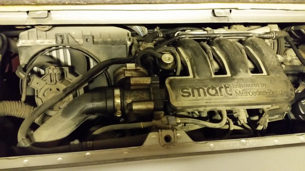
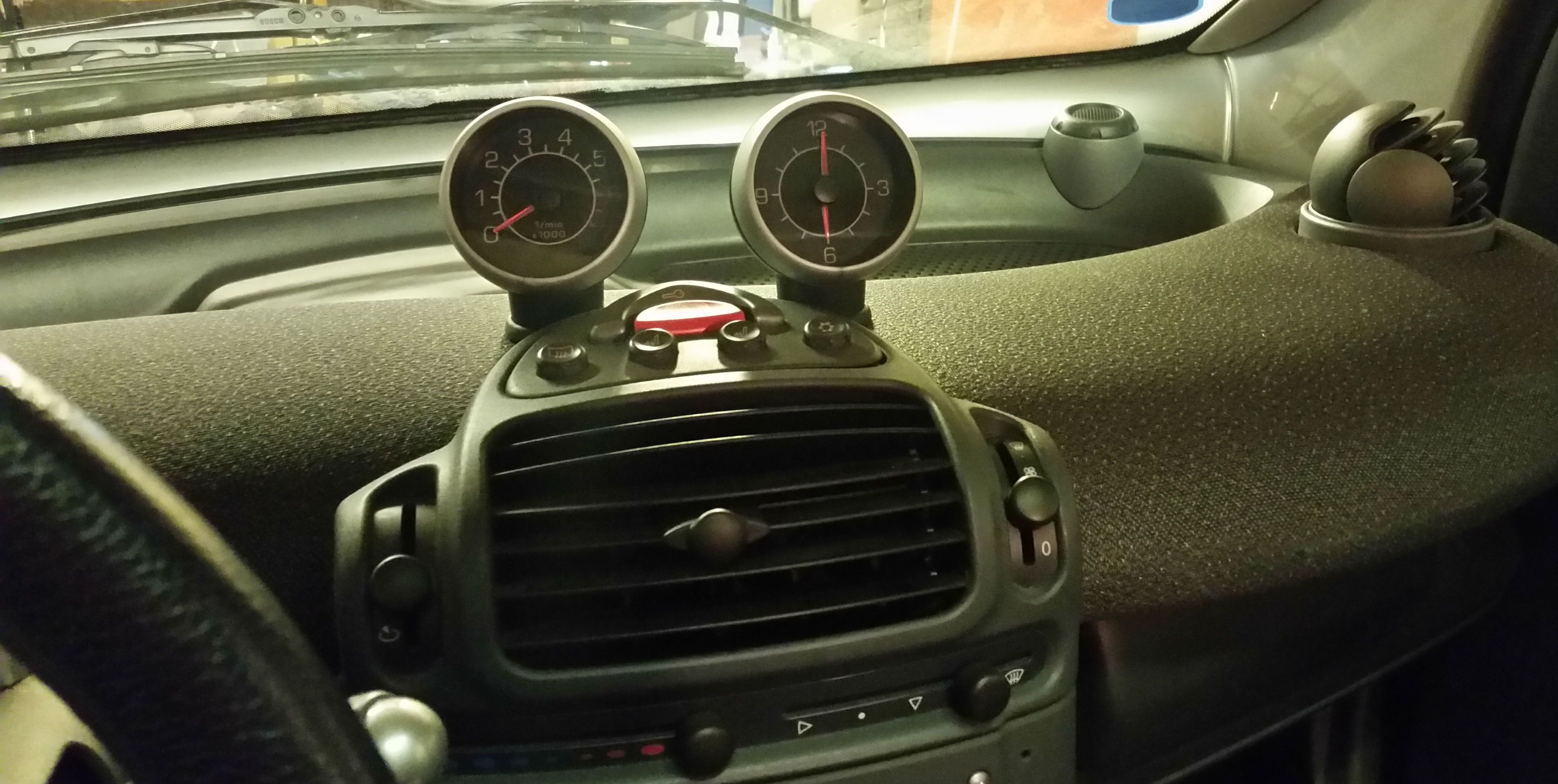
The initial plan was to install everything here.
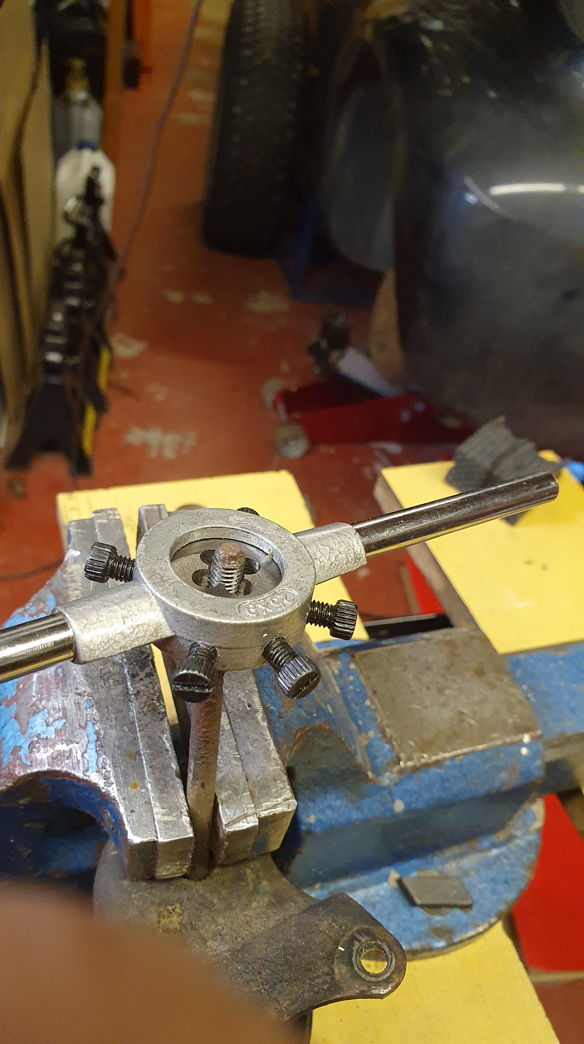
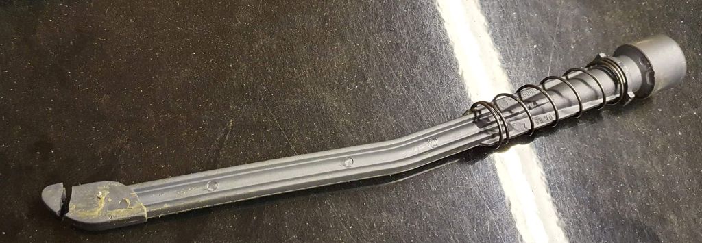
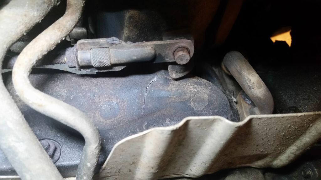
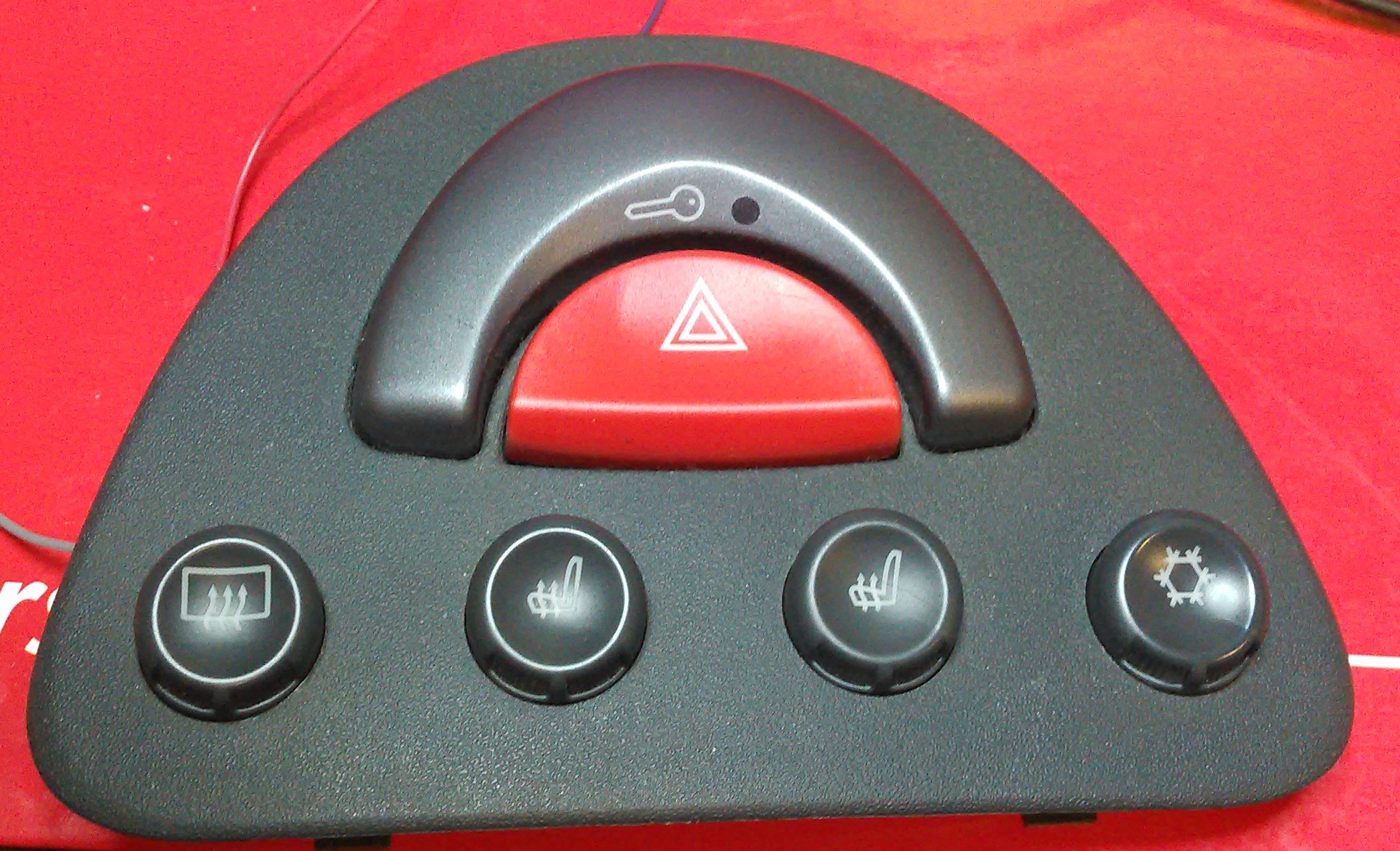
Started to work by removing the Safety Triangle and dissassembling it.
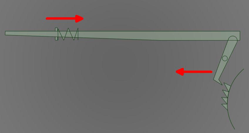
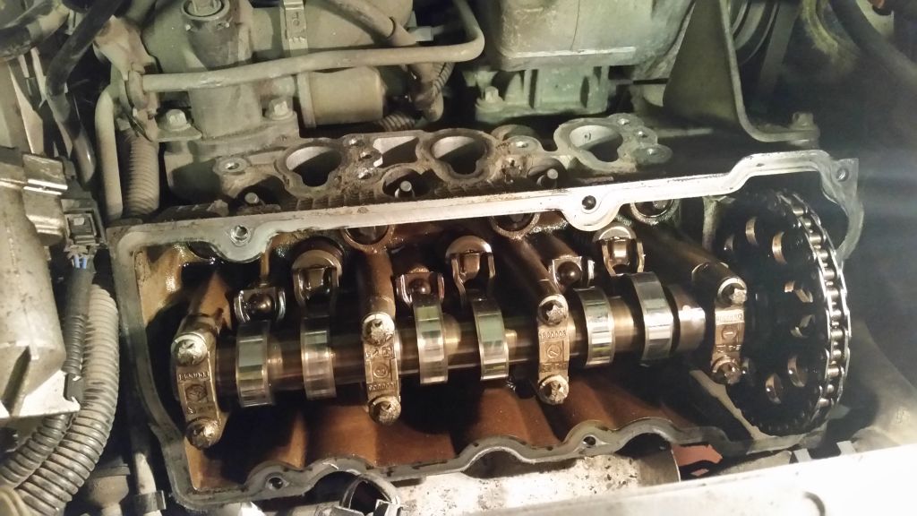
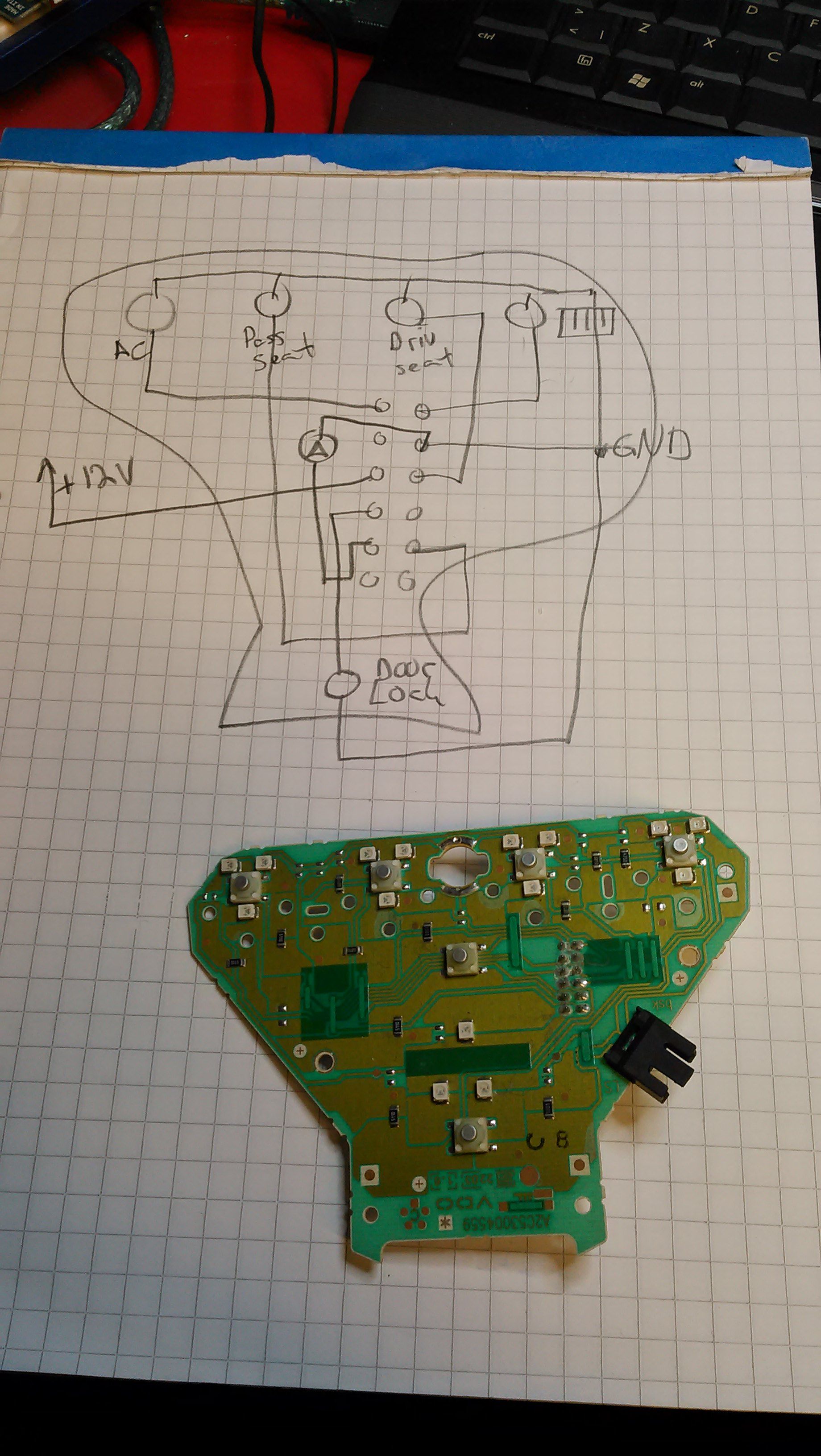
The journey continues by re-engineering.
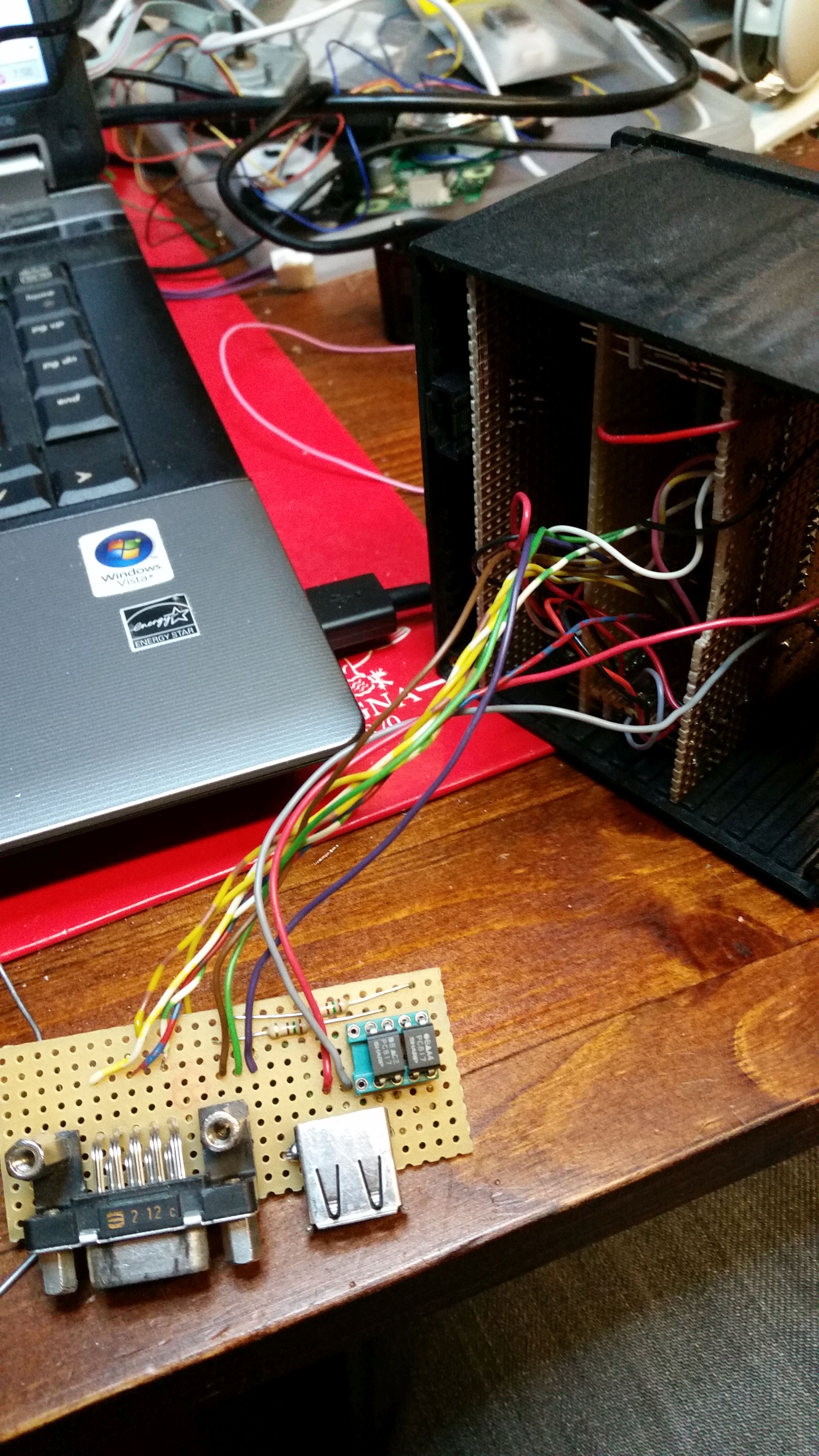
The very first version of connection board.
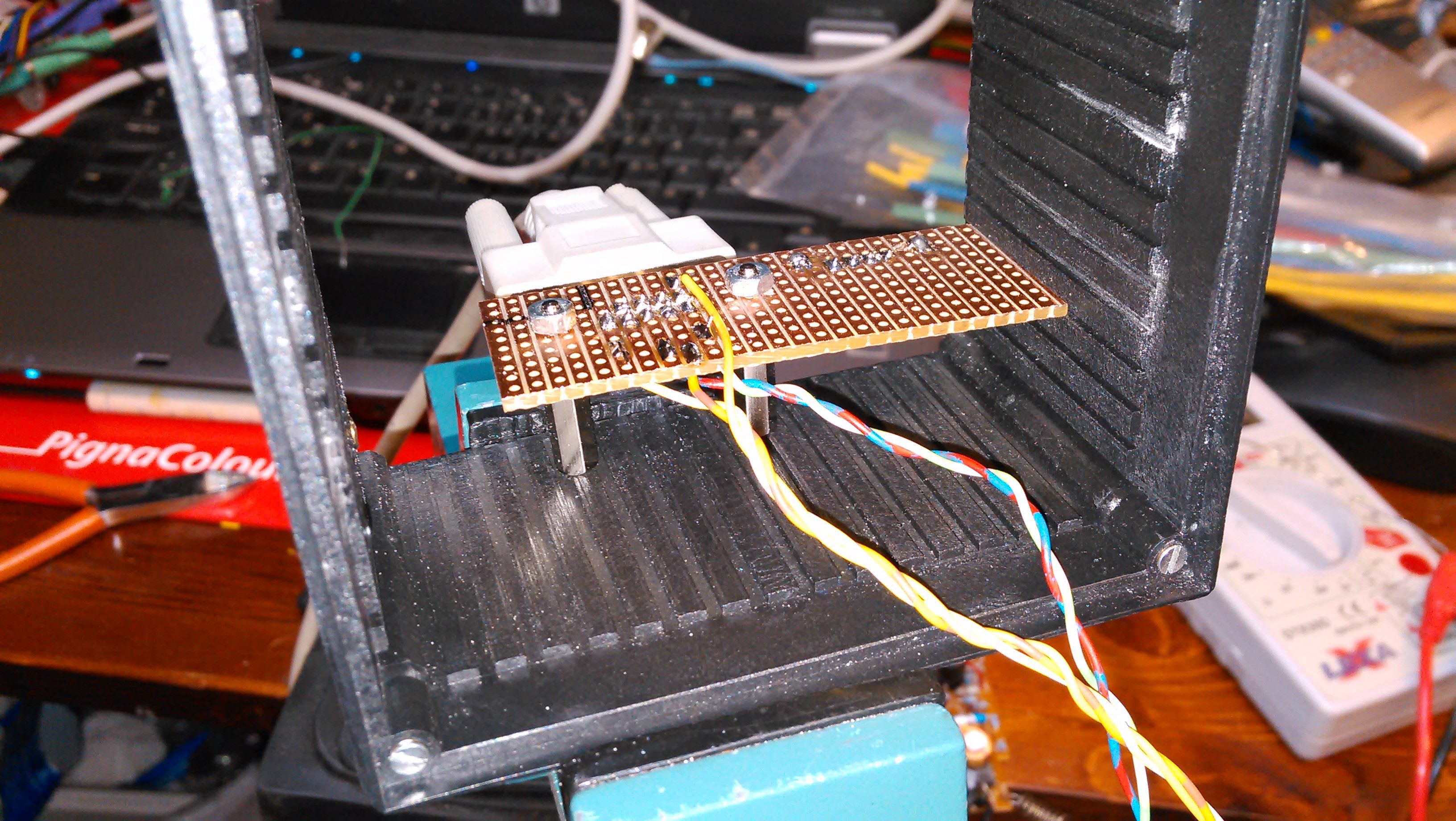
Here one can see it from another side. I planned to use PC817 optocouplers for isolation but along the way I switched to relays. More on that later. I took the liberty to use USB-connector for connection with car’s electric system. D9 is for rotary encoder.
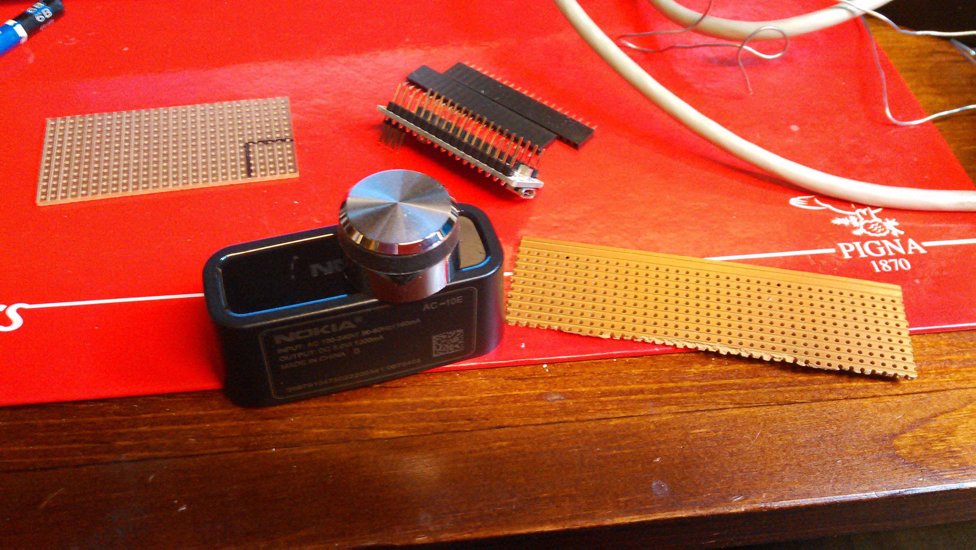
This is a starting point for house making to rotary encoder. Black case is from an old wall charger for Nokia mobile phone. Knob is from an old car stereo or something like that.
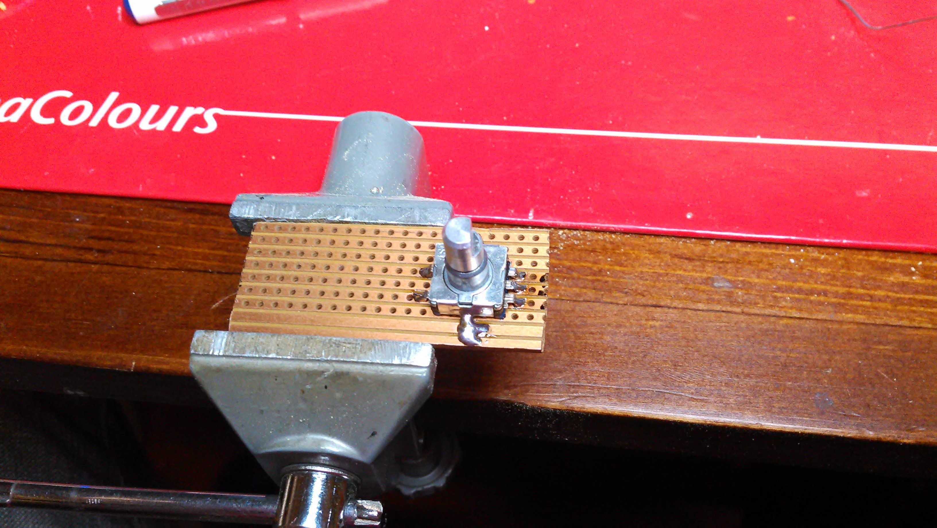
Here is a rotary encoder soldered in place. When I was continuing this build I realized that I should have put rotary the other way around, three legs pointing to left instead what it is now. Well, it happens to all of us..
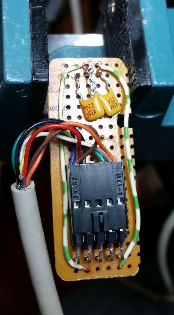
I also had to install capacitors to reduce interference. It still needs something, readings are not reliable enough.
There is something in the mess, I rarely see a workbench which is tidy and clean. Hmm, except Quin Dunki’s bench. Her work is amazing.
Anyway, some progress has achieved.
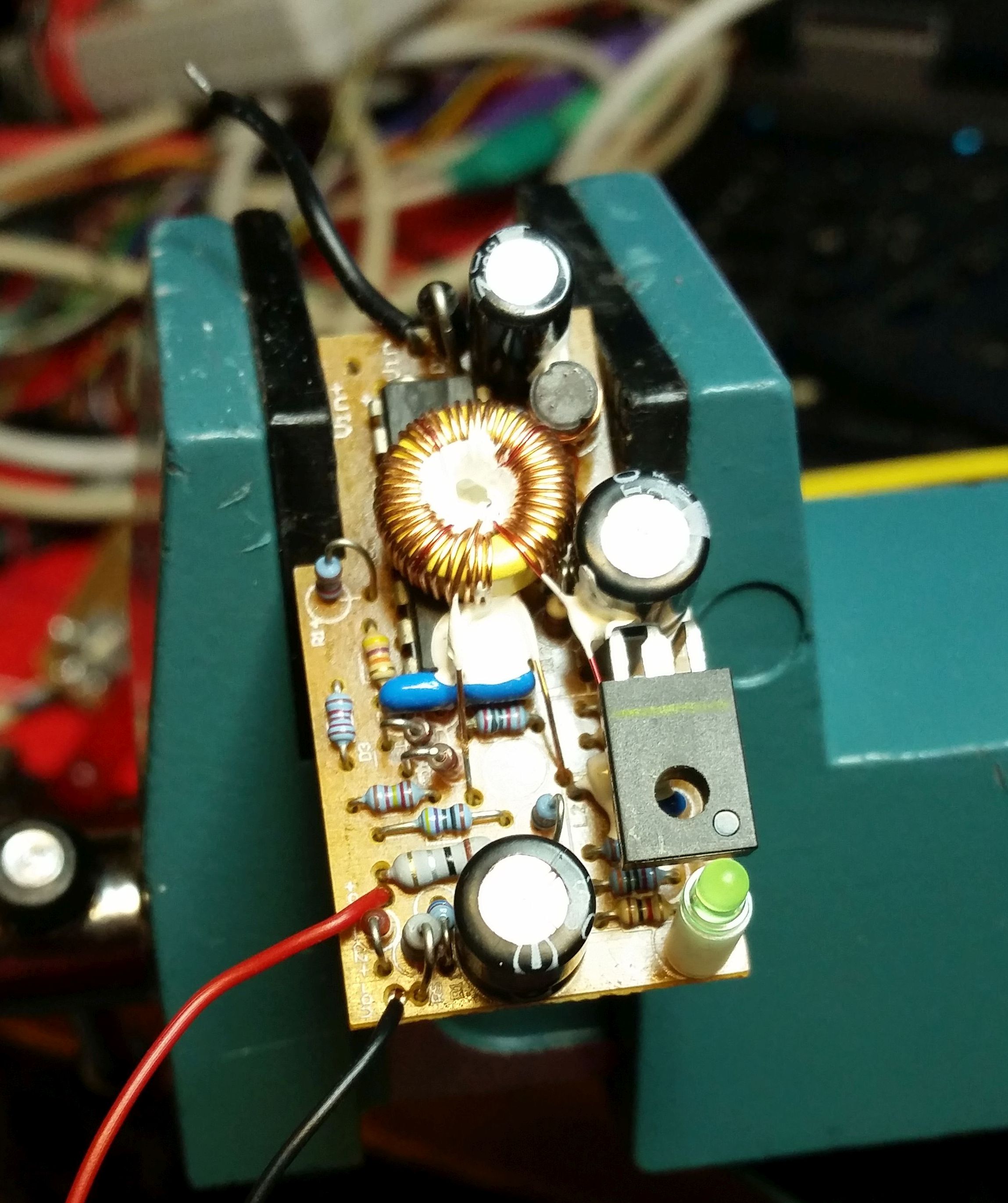
This is my power supply. In it’s early life it served as 12V mobile phone charger. Through this I can safely use my small embedded systems in electrycally noisy car environment.
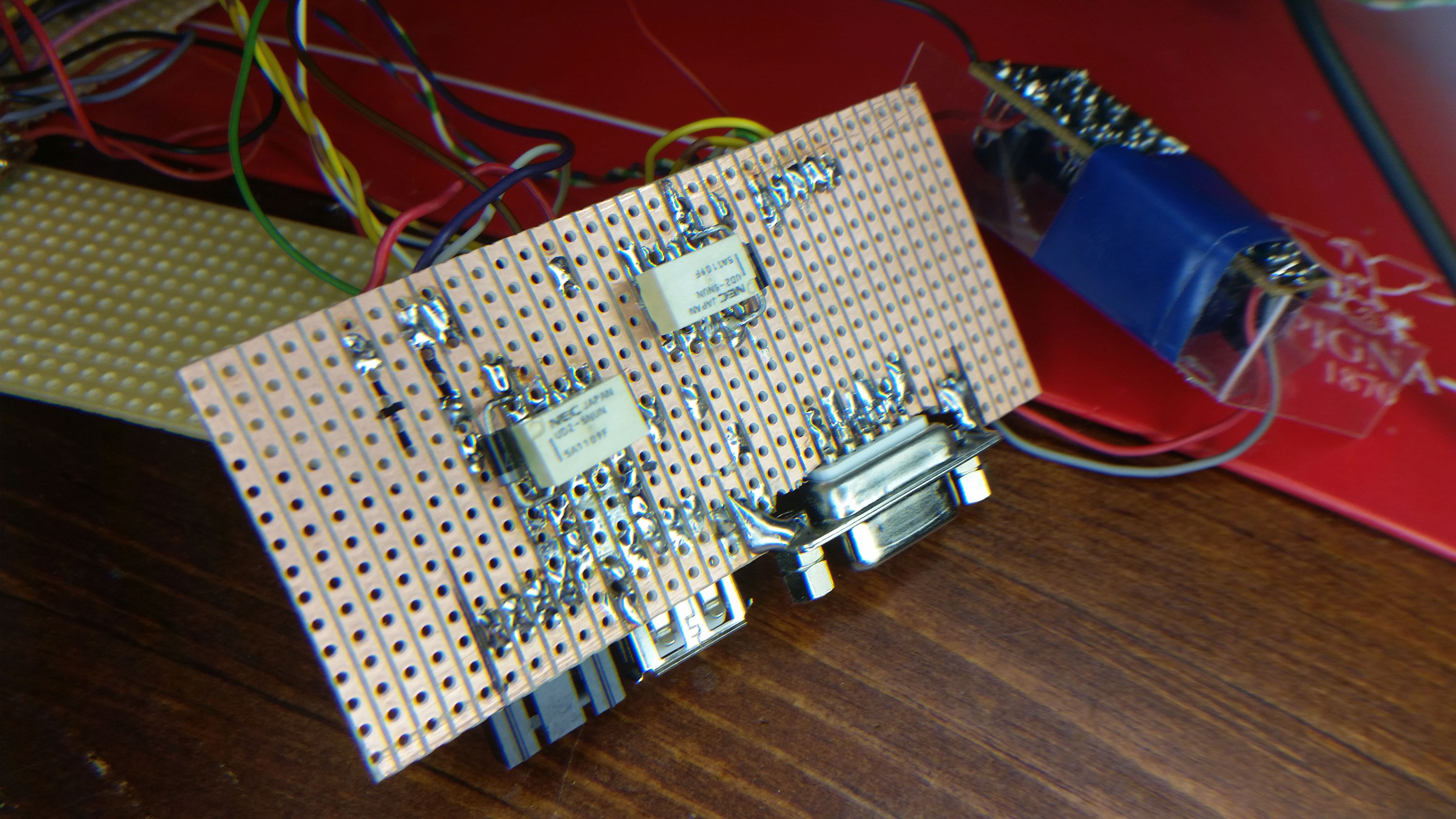
This is my new connection board equipped with relays. As mentioned, previous plan was to use optocouplers. I did not managet to get them work, maybe because of some my stupid coding error. Anyway, I switched to relays.
Those relays “push” the triangle’s buttons when commanded by Arduino. Smart has conveniently system I like very much: Pushbutton is ON-OFF state information for car’s computer instead of some resistance change. This way relays can be used to “push” buttons.
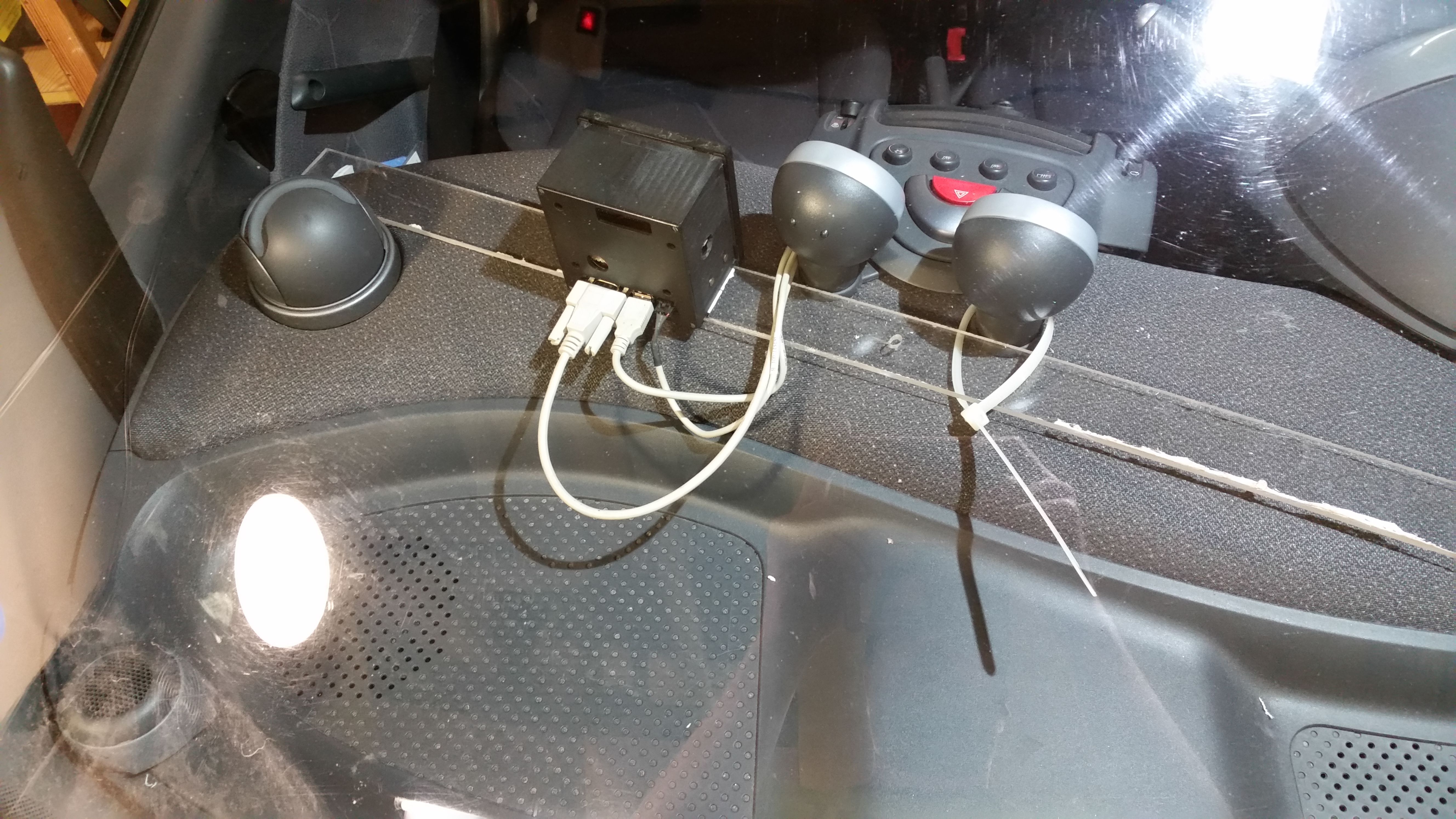
From left to right connectors are: Black: Temperature probe connection, USB: Power to my system and controlling buttons and D9 is for rotary as earlier mentioned. Temperature connector in salvaged from an old PC’s motherboard. It is an audio connector. In the future there might be coming a minor problem with D9. In the end of cable is a quite heavy connector and stiff car’s suspension combined with that weight might do some issues by removing solder joints during time. That is to be seen.
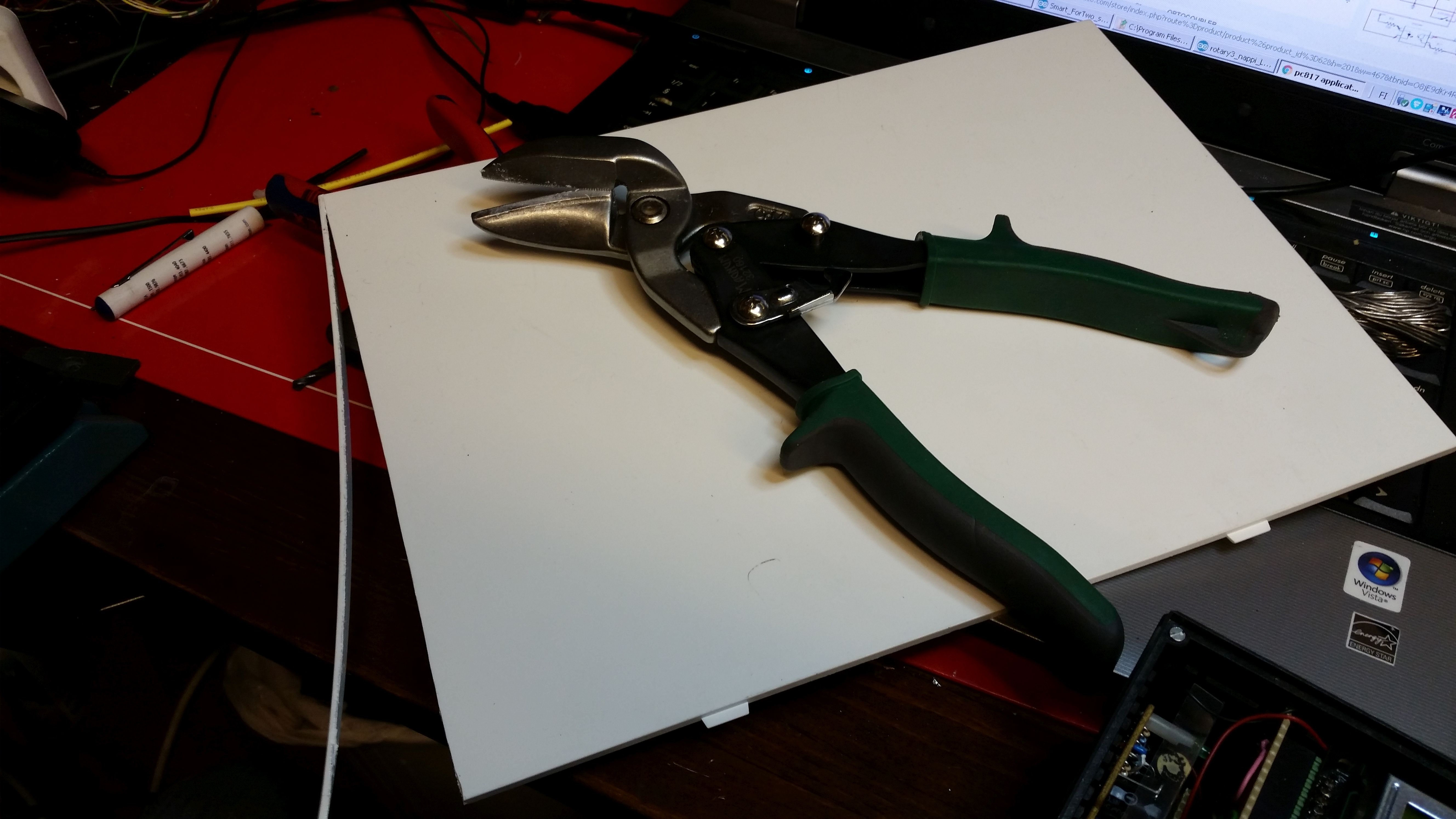
This is a starting point for facade. The white plate is salvaged from an old laptop LCD monitor.
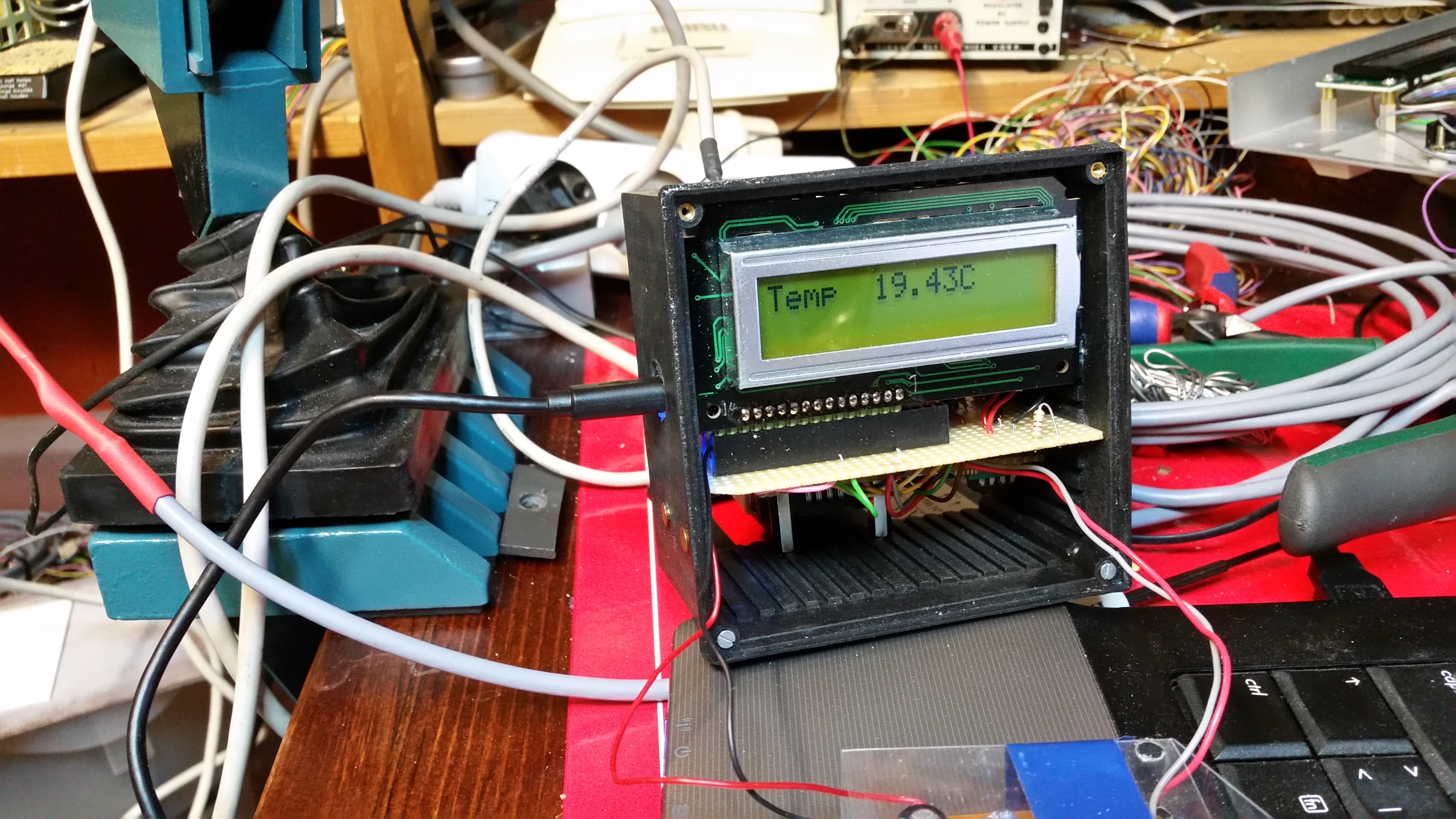
And here we are: Casing for encoder is ready, temperature sensor(red thing) is ready, main unit is ready. Now it only needs to be installed. And it maybe need some clever programming also. Now it is only a timer ) :
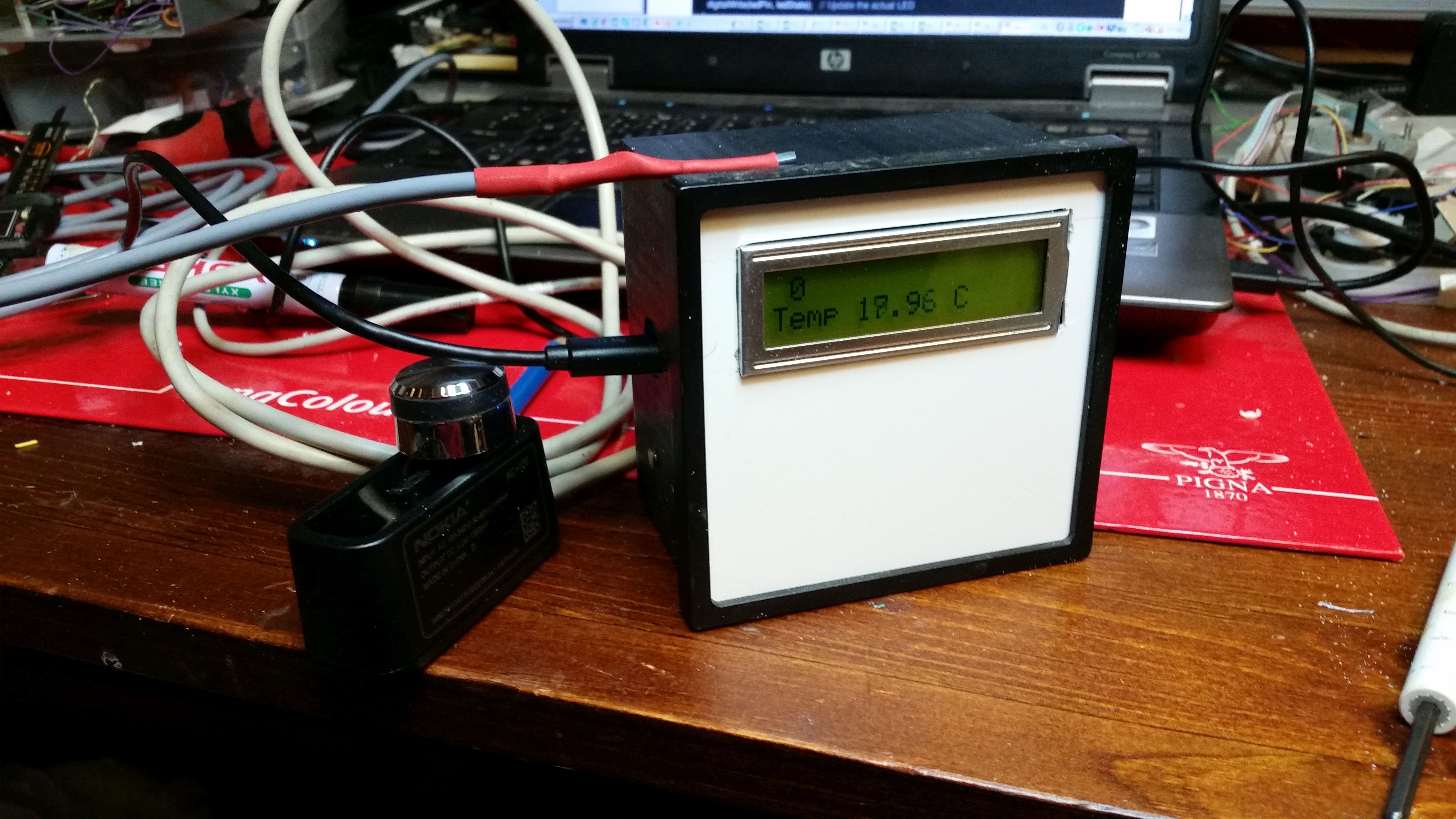
This is only temporarily mock-up.
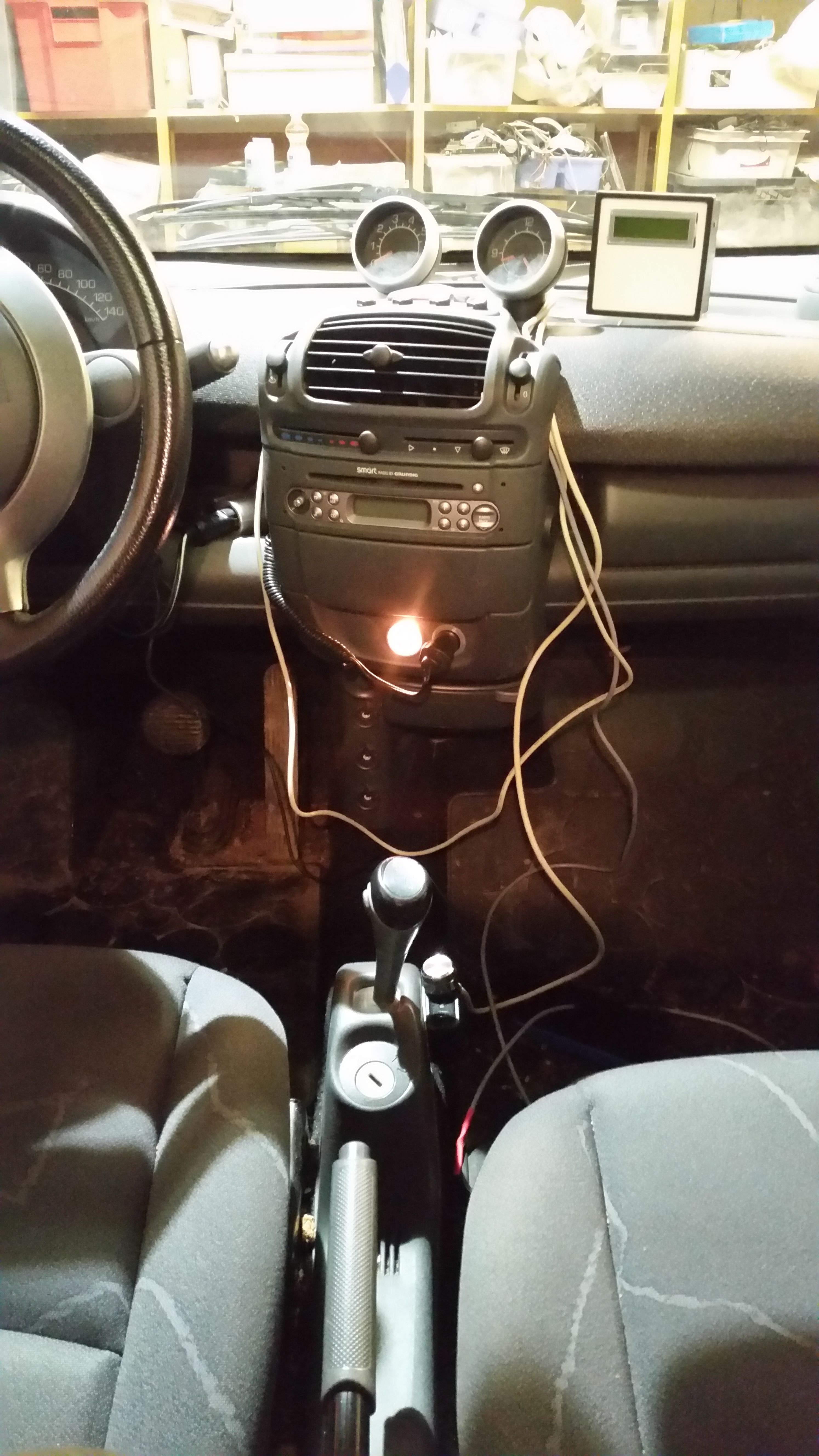
From another angle. When thinking how to install main unit on top of dashboard wisely(read: do not drill holes in that dashboard) I got an idea: Why not make a console in front of gear stick and stuff the whole system inside it? That way there is room for that earlier mentioned window-control also.
Yes, that is a good idea. But then again that means a lot of work and no automated seat heaters yet. And Summer is coming. Also, I finally want to enjoy the work of my hands. It has been a long building process. What to do? Naturally install the system. Temporarily, of course. 😉
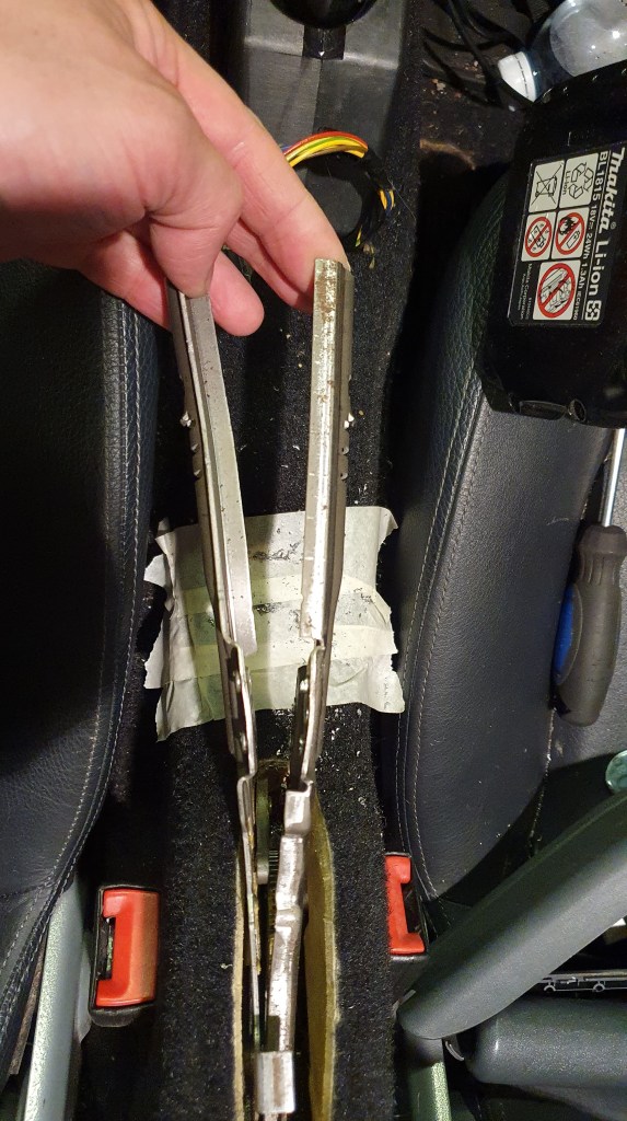
Encoder is located beside the gear stick. Temperature sensor is on the floor, for now. Wires needs to be sorted. But it works. Hooray!
Here is a link for video
That’s all for now!